Saturday, April 1, 2017

Checking.

Since my last post I had performed a further four trials with the average of all of them being -0.47% the accepted speed in air. It seems I'm hitting a wall in terms of the achievable accuracy with this setup.

Below is a capture of the noise present. Around the trigger point on Ch1 / Ds the timing is accurate, although I'll admit to not knowing at this stage why the apparent trigger is offset by about a nano second or less from the actual trigger point.

Anyway I used the cursors to mark the sweet spot on Ch1 and the expected 60.8ns ToF. From the Cursor B point we see a -4.8 and +8.8ns error. If we take the average of those two numbers we arrive at a potential +2ns bias in our results.


However if I adjust all the results by 2ns it goes way off to about +2.62%. That's to quick.

A bias adjustment number that does work perfectly though is about 0.5ns, hey wait a minute that's close to that weird offset between the trigger and the stable part of the wave? I wonder.


One strange thing I'll need to think about though is why does Ds always see a smaller signal then Df. The Start detector is on the reflect face of our beamsplitter but I brought a 50R/50T plate specifically so I would not see any difference?


I spent most of the afternoon swapping cables, scope channels, detectors around to reassure myself that they were all good and they are or at least within my ability to measure any difference. So I'm confident the signal is effected by the beamsplitter itself, I have it at the 45 degrees so what gives?


Monday, March 27, 2017

More results -0.0551%

EDIT : Funny story, when I first posted this the title was -0.0003% but after looking at it for a few minutes I realized I had in fact moved Ds by 10mm after I did the distance measurement. Clearly accurately measuring distance is going to be the hard and important factor here. I've corrected the numbers below to account for this.


I took extra care to reduce the amount of light hitting Ds by turning the beam off axis. Such that Ch1 (Ds) was 10V/div and Ch2 (Df) was 5V/div. This time I was triggering on Ds at just around first knee as I described in my last post (point A)

40 measurements in total, and I also recorded the required parameters to calculate the refractive index using the NIST tool

Air Pressure :1022 Bar
Temp :13.5 c
Humidity 72 %
Wavelength 532 nm

Giving n and c in air below.

n 1.000281673
c 299708038 m/s

From that I expect the round trip time to be - Yes I remeasured the distance again 

distance 18.2338 m.
expected 6.08385E-08 s

Here are the results.

Average : 60.805 ns
Error : -0.0551 %
Error : 3.3542E-11 ns
Speed : 299873366 m/s
Error : +165327 m/s

I'm going to look at the precision and errors later but just wanted to get this down on the blog. I would expect because the averaged time gives 5sf I can say I'm no worse then -0.0551%


Sunday, March 26, 2017

More results -0.74%

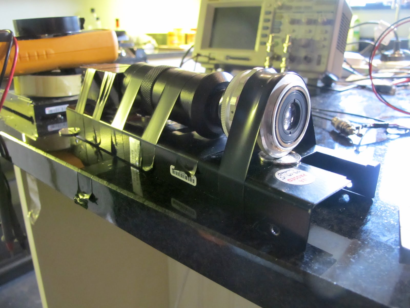
Today was spent just taking measurements and looking at the results to understand what is going on with the apparatus. This is setup 2 again with identical type 1 detectors into 50 ohms reversed biased with 25 volts.


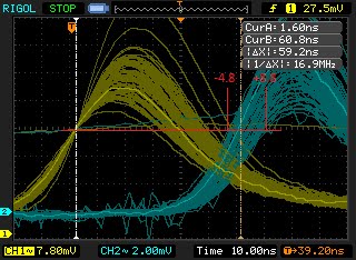
With persistence on we can see the noisy signals from the laser.. It's not such a good laser. Channel 2 (blue) is our Df detector running at the minimum allowable vertical sensitivity my scope can muster of 2mV.


I thought It worthwhile describing how I am taking measurements on the scope. Because we have a couple of mountains rather then fantastically sharp rise times I decided to focus on at least matching the wave forms after I stop the scope running.


1) get both wave forms in view and hit STOP on the scope.
2) vertically align the peek of CH2 to the nearest grid reference.


3) scroll horiontally to the left, select CH1 and vertically align it to the base line given by CH2. Note this can be a little tricky working in the noise but after about 200 attempts you develop an eye for the average.


4) Scroll horizontally back to the wave forms and now adjust CH1 vertical fine tune to the same grid reference we decided on in step 2)

5) Iterate steps 3) and 4) until both agree. Each time you scale CH1 the vertical alignment will be out a little.


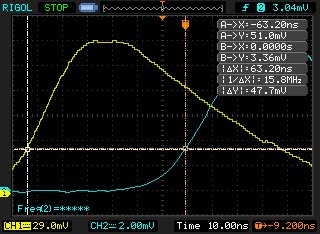
6) Get our your favorite tracking cursors and set B = 0s this is your trigger point and reference zero time measured by Df on CH2. Scroll A backwards until the two horizontal cursor lines intersect.


The theory here is that if both wave forms are vertically aligned, and both detectors are equal then the rise times should be equal and so we can derive the ToF. Here we see it as 63.2ns (a little out) but that's just one measurement.

To nullify the errors in our system we must sample lots of data and average and do statistics and stuff.

So I did some tests taking 20 measurements each time and averaging the results.

What I also did was measure my distance again and tested some other assumptions.

First the distance plays a huge role because my ability to measure it is limited, I'm using a 8 meter builders tape, dropping a plum line from my bench, marking the floor with electrical tape, running the distance to the wall, subtracting the distance from the wall to the far mirror (20mm) and all that to arrive at a new figure of 18.22m round trip after subtracting the 300mm to Df.  If I had to guess - because that's about the best I can do - I would say that I got it to +-10mm. But 10mm is 4sf so is going to really influence the results.

Second is the refractive index of air that I originally put at 1.000293 based on this Wiki page. NIST have a couple of calculators to get more accurate values. So my 532nm laser, at 300m above sea level, at 18 degrees centigrade I keep my house at and a guess at 50% humidity gives me 1.000265104. That modification changes my error by about 0.01% so not a big deal at this stage. But for reference that puts c=299713003

Once all was done I took 140 measurements over 7 trials, each trial involved a little modification to the measurement technique and scope setup. The worst one came out at 2.42% the expected ToF, while the best trial was -0.74% (negative error meaning the time was faster then expected).

How do I account for faster than light measurements? Well all I can think of at the moment is some difference in rise times between the detectors. I'm going to do several more runs to get confident in the consistency of my measurement before I swap the detectors, that requires alignment of everything again.

All in all I'm really happy with the results thus far, despite the best error representing a 2242582m/s difference. Only 7 figures to go now :)

I found that where on the Ds waveform you obtain a trigger point has an effect. I have marked the three locations I tried below. As the wave rises from it's ground reference point we first get a knee at A rising through B at 50% and ending at the peek passing through C.

Point B is where we have the maximum dV so should be the best place to look, and that was proven true by improved accuracy when I increased my trigger voltage to about the mid point. However by the same token point B and C is where rise time errors would be most pronounced.


Saturday, March 25, 2017

laser collimation

The difference in the amount of light reaching my two detectors was causing huge problems in my ability to take measurements. Ds would be full beam reflected off the beam splitter, while the light getting back to Df was washed out due to divergence in my laser diode over the distance.

My first attempts revolved around using a lens to directly focus the reflected light on to Df. The real solution is collimation of the beam at the source rather then trying to fix the error at the end.

So here it is, the beast. The laser is on the left, in the middle is the microscope objective, and right is my old camera lens. With this setup I am able to get a 10mm beam diameter over the 9.2m distance. Consequently the return beam is more sharp.


The Df detector seen below still receives it's final signal from a tinny little lens I had from another old camera.


Also as mentioned I was going to improve my cables and correctly terminate the lines with 50ohms so that's what I did. The old RG58 cable is gone and replaced with two new identical RG316 ones, t-split with standard 50ohm loads on top.


So far as measurement goes I have found a few things to improve upon the previous method.

The first is to reduce the amount of light hitting the detector Ds to about the same level that Df is seeing, my hope is this would normalize any rise time effects.

The second was to verticaly match the two waveforms after capture and take a measurement from the actual trigger point on Df and then taking the same point from Ds vertically.

Here is 62.0ns over the newly measured distance of 18.2m


And 60.8ns.


To get less light to Ds I am just holding it slightly off axis and hitting the stop button when they are close.

Next I am going to take lots of measurement's and see if I can get a reasonable average.


Wednesday, March 22, 2017

Setup 2 - Again.

I repeated the setup tonight and got a much closer time by carefully aligning all the optics and looking only at the instantaneous rise of both detectors.


Again this is not a measurement. The 60ns gap of the cursor's is just aligned to what I expect. I am maxing out confirmation bias here.

Tuesday, March 21, 2017

Setup 2 - And Results

I managed to get a few blips on the scope that look like something close to the expected 60ns I'm after.

Over the 18 meters return trip 65.6ns brings me to within 8% to the actual speed. However I understand this is not a 'measurement' in the sense that I have plenty of variables yet not accounted for. At this stage I'm happy to call it blind luck more then anything.

First of all I saw the two peeks and just arbitraerly decided that was the place to measure. Given the huge difference in vertical scales between the two it's hard say if Df (channel 1) would have risen faster if only it were getting the same amount of laser power as Ds.


What I would like to do is measure at the earliest sign of the signal rising off the floor, but as you can see that's not so easy to spot.

Below is the physical setup, you can see the old camera lens I'm using to focus the faint light from the mirror onto the junction of Df.


What I changed this time around is both detectors are identical now, previously I had three different ones that I was playing around with. The ones used here also differ to that described previously and are now just a photodiode with a 330 ohm load. The reverse bias is still 25 volts.

I'm using 330ohms only because I did not have any 50 ohm ones on hand. The plan is to use a proper 50 load at the scope end of the cable and remove R1 from the circuit above.

So I have three detector types

D1: Is the first one I built and described here, in a metal box.
D2 : Is the same as D1 but with C1=100pF and free floating without a box.
D3 : Is the one above that I used in this setup, and also not in a box yet.


The first improvement I want to make next is get some good duplicate cables between the detectors and the scope. Currently I have one stock scope probe, and the second cable is RG85 coax of a different length with reversed protection diodes. I've ordered some RG316 to make two new cables.

The second change is to investigate the how the amount of light reaching Df and Ds affects the response time. To solve that I'm really going to need to collimate my source beam or perhaps use a beamsplitter with a different ratio to the 50/50 one I have now, something more like 90/10 might work.


Sunday, March 19, 2017

Setup 2 and no results.

As mentioned in the Setup 1 post my laser has some crazy concepts of time that I would like to eliminate. So below is the new setup I am running. We now have two detectors Ds (start) and Df (finish). So it does not matter when the beam exits the laser because our scope trigger is now just when ever it does.


And here is what that looks like.. man, I need a proper optics bench. The green line is the laser path, note the washed out mess that is the return beam to Df.


Here is my precision retro-reflector at 9 metres from the laser. Observe, a small copper tube is exactly taped to my chimney upon hangs a dimension retarded mirror via rubber band strop with disposable external hard drive for fine alignment. Well it works.


What does not work so well is the beam divergence against about A4 paper.


What does get back to Df is faint, so I'm using a lense to focus what is returned on to the detector. I'm finding though that with less light comes lower rise time so at this point I'm not able to make a measurement.

At 18 metres I'm starting to think 60ns is getting a bit beyond what I'm capable of with the equipment I have.

Detector

The detector I am using is a reverse biased PIN photodiode, specifically a Centronic BPX65.  Just a word of caution many manufactures make a photodiode called a BPX65 and they are not all the same, pay special attention to the max reverse bias voltage and do not exceed it!

The ones I'm using have a response time down around the 3.5ns range.


On the front plate of the box I have drilled a hole that lines up with the photodiode that is just floating inside the enclosure. At the back we have a BNC and power jack.


The internals are quite simple. The two images below are from a concise and good OSI datasheet.


I constructed the coax cable as described with the two protection diodes at the scope end. Powered from my bench supply at Vbias=25V. The yellow trace is the square pulse (short little blip) from my PWM driver about 8us that triggers the laser with the hot end pointing directly at the detector - the blue trace.

The first time I built this I used Rs=10Gohm and C1=68pF

On the left of the detector trace we can see the ground voltage that is a result of the dark current that comes about when these things are reversed biased. The main thing I'm checking here is that for a given PWM period the detector is able to recover fully prior to the next pulse.


Just because I like making life hard for myself my laser is 523nm that is not so close to the peek sensitivity of the BPX65. If you do a parametric search at your favorite electronics shop you'll find that most of the devices available are for 900nm and above. Devices at my wavelength were either cheap and slow or very expensive and did not quote response times?


Anyway once I was all setup this is what I found, the best rise time I cold muster was 168ns.


In this configuration the peek voltage (about 372mV in my case) depends on the amount of light that falls on the detector, that in turn seems to have a serious effect on the rise-time. It does not matter how wide your PWM pulse width is because that is never going to change the instantaneous energy the photodiode sees.

Next I reduced the resistor such that Rs=1Mohm and C1=68pF, and dispite the overshoot I was getting 60ns.


This could be improve upon to 50ns by putting a lense in front to focus the beam at the detector junction.

I ruled out the coax being at fault by connecting the standard scope probe and got a nearly identical waveform. So that leaves the following variables I need to workout.

Depending on what rule we use my 100MHz scope should be able to give a 0.35/100MHz= 3.5ns rise time so the two unknowns here are the detector itself and the laser. Currently I have no way of knowing the rise time of the laser so might look at a toothed wheel setup rather then the PWM and see what difference that makes.

I will also get a red laser and see it the photodiode response time is affected by wavelength.

I have a few of these photodiodes on hand so will be building new detectors with them - Marktech MTD5010W

Saturday, March 18, 2017

Setup 1 and results.

So actually I did this last year and after an initial fail and being distracted by other things I put it away.

I'm using a Raspberry PI as my driver for the laser's PWM input. This allows me to control the total power in the beam. Ds triggers my oscilloscope while Df my photo detector is connected to the second channel.

I thought this would be good enough to get started if it were not for some lazy characteristics of the laser itself.

First problem is the delay in the laser. Once the PWM goes high, as seen by the yellow trace, it takes about 3.8us before the beam comes out and gets detected. I tested this by placing Df at the laser.


Replacing the laser with an off the shelve LED shows a significantly faster response. 


Now the delay in the laser would not be a problem so long as it were consistent... of course it's not! Looking closely at the jitter on Df. again with the detector hard against the laser. All the fuzzy stuff is the +-95ns error between when I tell the laser to turn on and it actually does.


Given the distance I'm working at is about 18 metres (60ns ToF) the jitter we are getting is a killer. 

In the second setup we'll see how a beamsplitter and second detector is used to exclude this error from the system. 

My First Beamsplitter - Damaged.

Note to self : balancing the plate on a coin near the edge of a bench above a ceramic tile floor is likely to end in disaster.

Well in this instance I managed to take a chip our of the corner of it.

Friday, March 17, 2017

My First Beamsplitter

Ordered and arrived two days later - a 50R/50T Non-Polarizing plate beamsplitter from Edmund Optics at £29.75 each I think it's one of the cheapest things they sell.

The beamsplitter does what the name suggests reflecting some light and allowing the rest to pass through. They come in different ratios and mine is 50R (% Reflect) / 50T (% Transmit). The ratio is specified at a particular angle of incidence and wavelength so it's good to check for your specific setup. But as I'm going to be at the defined 45 degrees it's all good.

Here you can see I donned blue latex for the occasion, not wanting to immediately destroy it with my dirty mitts. How I might mount it is a completely different question but have seen some cheap slide clamps that might do the trick.

Fig 2. 50R/50T plate beamsplitter
I was looking at cube splitters also but they are starting at £120 so I thought I would go cheap while still avoiding ebay at the same time. 

If you want a free one and have a dead CD-ROM / DVD-R drive you can recover a tiny 3mm square one however I have no idea of their properties but have a few kicking around.

Thursday, March 16, 2017

Fundamentals'ish

So starting out we need to know a few basic fundamentals about the experiments I am wanting to perform, and the limitations of what can be done.

The one fact we know - the SI unit for c in a vacuum is 299'792'458 m/s

We will be sending a pulse of light from a source to a mirror some distance away and attempting to measure the time it takes to complete the round trip. This is the Time Of Flight (ToF) method used for over a hundred of years.

What I have at my disposal is a Rigol DS1102D 100MHz - 1GSa/s oscilloscope that is somewhat limited by the stock 60MHz bandwidth probes.

I have a mirror of unknown origin sellotaped to the fireplace 20 metres away. Your getting the idea.

I have a (apparently fancy) 532nm 150mW laser diode that I kind of splurged on with out thinking. That will be the bane of my life, I'll discuss later. It has a TTL input that I have connected my trusty Raspberry PI's hardware PWM output to.

The PWM output is the trigger of my oscilloscope channel 1 and the TTL input of the laser. I have constructed a photodiode detector that connects to channel 2.

I will talk about all these things in more detail in future posts.

An interesting question that never gets talked about because apparently it's just 'so obvious' is why do all these experiments use a mirror to return a pulse back to the source? Well it's very hard to synchronize two clocks at a distance to the accuracy we need. If we had a detector 20 metres away and sent a signal back to our single clock then how would we transmit that information? copper wires are slower then the light we are sending...

We will be working at around 1 atmosphere so need to adjust our value of c for that by taking in to account the refractive index of air. That's 1.000293 at 1 atmosphere at 0 degrees centigrade. Getting a number for room temperature at higher pressures and at my lasers specific wavelength looked like a whole world of hurt after a little googling so I will defer that and let the number lie for now.

Our corrected c_atmos = 299'704'645 m/s. A whole 87'813 m/s slower - That's HEAPS!

That means over my 40 metre distance I would expect the ToF to be 133.464732 nano-seconds.

Notwithstanding the finer details of oscilloscope bandwidth limitations I'm just going to take the reciprocal of our 60MHz probe to be the worst case in the system and say that the minimum time I could measure is 16ns and worry about the detail later.

So our error will be between 133ns and 149ns. That is ONLY a 32'082'982m/s error.. HEY were within the 11% range I can live with that for a first attempt.

Well, lets just suck it and see.

A Little History

Come 1676 Ole Rømer and Jean Picard were timing the orbits of Jupiter's moon Io and noticed a dependency in the data that could only be accounted for if the speed of light was not infinite, as was the common belief at the time. Others who analysed the data came to a number around 300000 km/s, not bad.

In the mid 1800's two french physicists, who were not unknown to each other, created two experimental setups to more accurately determine the speed of light. Hippolyte Fizeau used a rotating disk with cut notches over an 8km distance to arrive at a speed of 313000 km/s (10% error) while 13 years later Léon Foucault arrived at a speed that was within 0.6% of the currently accepted value using a rotating mirror on a much smaller scale.

Both methods are detailed here with the later being employed to educate undergraduates on the subject.

More accurate measurements were performed by Michelson, Pease and Pearson in the 1930's inside a 1 mile long vacuum. Their apparatus was based on Léon Foucault's rotating mirror design and an arc lamp as a light source. The eventual number of 299'796 km/s was arrived at.

What is mind-blowing for me about all the above methods is that they were performed without the aid of lasers as a light source.

The WIKI page has a great write-up on the different modern methods and more of the people from history that I excluded here https://en.wikipedia.org/wiki/Speed_of_light

A third way to measure c, aside from the Time of Flight and Astronomical methods used in the above examples, can be found by the product of wavelength and frequency of an electromagnetic wave. Such methods include the accurate measurement of capacitance, standing waves inside metallic cavities, and interferometry.

Today the speed of light is a fixed international standard set at 299'792'458 m/s and is in turn used to define a metre. Luckily we can avoid the paradox of a second being the time it takes light to travel 1 metre given it is defined as "the duration of 9 192 631 770 periods of the radiation corresponding to the transition between the two hyperfine levels of the ground state of the caesium 133 atom"

The fixing of c, I have read, was so scientists could spend more accurately measuring a metre. Probably because measuring time accurately is a far simpler proposition.

So the 532nm laser I have should have a frequency of 563THz if all is good and well with the world.


Wednesday, March 15, 2017

Introduction

So physics is cool and something I like to mess about with, so this blog will be a record of my adventures. The ultimate goal is to replicate the Delayed Choice Quantum Eraser experiment because it blows my mind! To get to that point I needed to start with a smaller goal of just measuring the speed of light in air as I feel it will teach me a lot about optics, detectors, measurement, and experimental techniques. 

As you can see from the picture below things are rather rudimentary at the moment. This is a 'in my spare time' project at home and on a budget.

My background is in electronics so I do not have any physics degrees to my name. Perhaps some comments along the way by readers will assist.

Fig 1: The Lab